Mechanical,
Thermal, and Mobility Subsystem
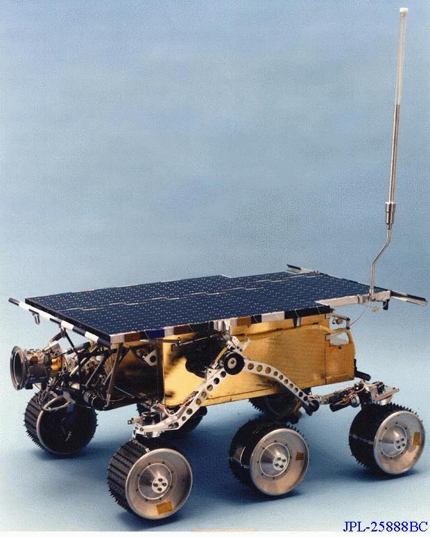
The microrover is a 6-wheeled vehicle of a rocker bogie design which
allows the traverse of obstacles a wheel diameter (13 cm) in size.
Each wheel is independently actuated and geared (2000:1) providing
superior climbing capability in soft sand. The front and rear wheels
are independently steerable, providing the capability for the vehicle
to turn in place. The vehicle has a top speed of 0.4 m/min.
Microrover components not designed to survive ambient Mars temperatures (-110 degrees Celsius during a Martian night) are contained in the warm electronics box (WEB). The WEB is insulated, coated with high and low emissivity paints, and heated with a combination of 3, 1W RHUs, resistive heating under computer control during the day and waste heat produced by the electronics. This design allows the WEB to maintain components between -40 and +40 degrees Celsius during a Martian day.
Control and Navigation
Subsystem
Control is provided by an integrated set of computing and power
distribution electronics. The computer is an 80C85 rated at 100 Kips
which uses, in a 16 Kbyte page swapping fashion, 176 Kbytes of PROM
and 576 Kbytes of RAM. The computer performs I/O to some 70 sensor
channels and services such devices as the cameras, modem, motors and
experiment electronics.
Vehicle motion control is accomplished through the on/off switching of the drive or steering motors. An average of motor encoder (drive) or potentiometer (steering) readings determines when to switch off the motors. When motors are off, the computer conducts a proximity and hazard detection function, using its laser striping and camera system to determine the presence of obstacles in its path. The vehicle is steered autonomously to avoid obstacles but continues to achieve the commanded goal location. While stopped, the computer also updates its measurement of distance traveled and heading using the averaged odometry and on-board gyro. This provides an estimate of progress to the goal location.
Power Generation and
Distribution
The microrover is powered by a 0.22 sqare meter solar panel comprised
of 13 strings of 18, 5.5 mil GaAs cells each. The solar panel is
backed up by 9 LiSOCL2 D-cell sized primary batteries, providing up to
150 W-hr. This combined panel/batteries system allows microrover power
users to draw up to 30W of peak power (mid-sol) while the peak panel
production is 16 W. The normal driving power requirement for the
microrover is 10 W.
Radio Communications
Command and telemetry is provided by modems on the microrover and
lander. The microrover is the link commander of this 1/2 duplex, UHF
system. During the day, the microrover regularly requests
transmission of any commands sent from Earth and stored on the lander.
When commands are not available, the microrover transmits any
telemetry collected during the last interval between communication
sessions. The telemetry received by the lander from the microrover is
stored and forwarded to the earth the same as any lander telemetry.
In addition, this communication system is used to provide a
'heartbeat' signal during vehicle driving. While stopped, the
microrover sends a signal to the lander. Once acknowledged by the
lander, the microrover proceeds to the next stopping point along its
traverse.
Commands for the microrover are generated and analysis of telemetry is performed at the microrover control station, a Silicon Graphics workstation which is a part of the MPF ground control operation. At the end of each sol of microrover traverse, the camera system on the lander takes a stereo image of the vehicle in the terrain. Those images, portions of a terrain panorama and supporting images from the microrover cameras, are displayed at the control station. The operator is able to designate on the display points in the terrain which will serve as goal locations for the microrover traverse. The coordinates of these points are transferred into a file containing the commands for execution by the microrover on the next sol. In addition, the operator can use a model which, when overlayed on the image of the vehicle, measures the location and heading of the vehicle. This information is also transfered into the command file to be sent to the microrover on the next sol to correct any navigation errors. This command file is incorporated into the lander command stream and is sent by the MPF ground control to the lander, earmarked for transmission to the microrover upon request.
For more information on the Microrover Flight Experiment, see the papers [MATIJEVIC1994] and [MATIJEVICETAL1997A].
Copyright 1996, Jet Propulsion Laboratory, California Institute of Technology and the National Aeronautics and Space Administration.
Related Information
The following links provide some additional information about topics
related to the Mars Pathfinder mission. You must be connected to the
Internet for most of these links to work, since they are located at
the Central Node of the Planetary Data System.