MFEX Rover
System and Operations Overview
Updated 8/21/96
- Meet cost, mass, and schedule requirements
- Minimize rover impact on Pathfinder project cost and risk
- Survive launch, cruise, landing
- Perform surface operations
- complete technology experiments
- carry out APXS rock and soil measurements
- image lander
- Operating range:
- operate primarily within 10 meters of lander
- drive up to 100 meters on the Martian surface
- be capable of operating beyond lander's horizon
- Lifetime:
- complete 7-sol primary mission
- be capable of extended mission up to 30 sols duration
To meet its mission objectives, the Microrover Flight Experiment (MFEX) rover must be able to:
- Communicate with lander to request commands and downlink telemetry
- Wakeup in response to either lander or on-board triggering
- Execute command sequences
- Unstow itself and drive down the lander ramps
- Traverse the surface of Mars while detecting and avoiding hazards
- Reach targets of interest as designated by Earth-based operators
- Maintain knowledge of its internal state
- Operate on-board experiments, including the APXS, MAE, and WAE
- Manage its limited available power
- Maintain its internal temperature within acceptable limits
- Perform a useful contingency mission if communications is lost
- Recover from command execution failures
- Continue to operate in the event of hardware degradation
Rover Operating Characteristics:
- a simple spacecraft
- a serial machine - "Can't talk and chew gum at the same time"
- operates in a non-deterministic environment - each step may yield unexpected results due to unknown terrain conditions
- event driven
- many commands (e.g., waypoint traverse) have significant (although bounded) uncertainty in execution time
- command execution start time is determined by time of completion of previous command
- rover sequences can be re-synched with lander activities by insertion of "Wait" commands at appropriate points in sequence
-
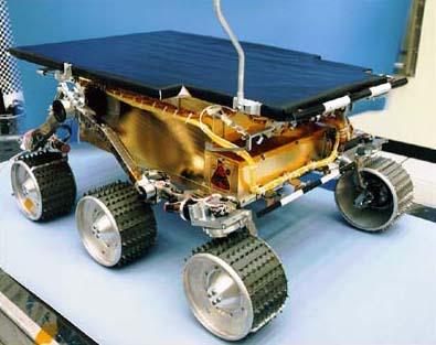
Physical Characteristics:
- Rover mass: ~11 Kg
- LMRE mass: ~5 Kg
- Rover dimensions (deployed): 63.0 cm (L) x 48 cm (W) x 28.0 cm (H)
-
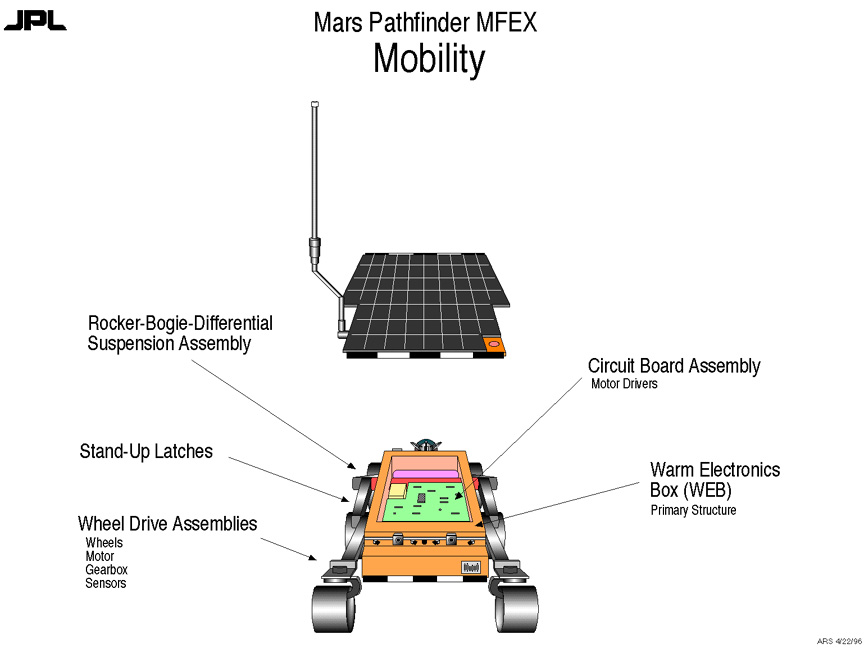
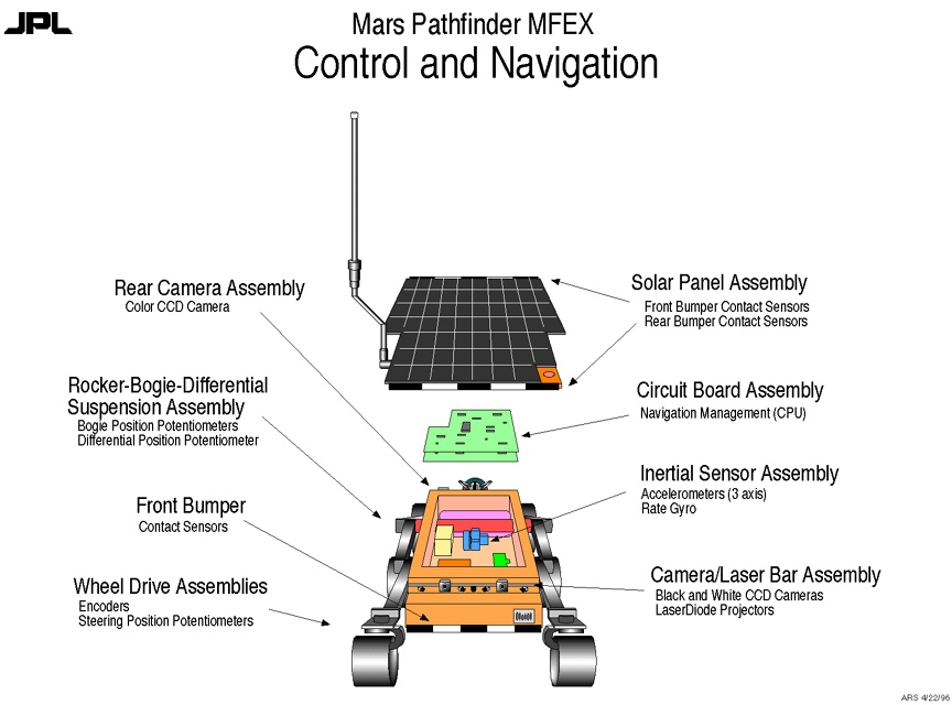
Mobility
- Rover mobility hardware elements
- Rocker-bogie chassis design
- 6-wheel drive, 4-wheel steering
- Rover speed ~0.4 meter/minute in nominal terrain
- Vehicle capable of driving over obstacles 1.5 wheel diameters high
- Rover can turn in place
- Rover stowed flat during cruise to minimize volume
- After release, rear wheels drive forward, raising rover to full height and locking rocker arms in deployed configuration
-
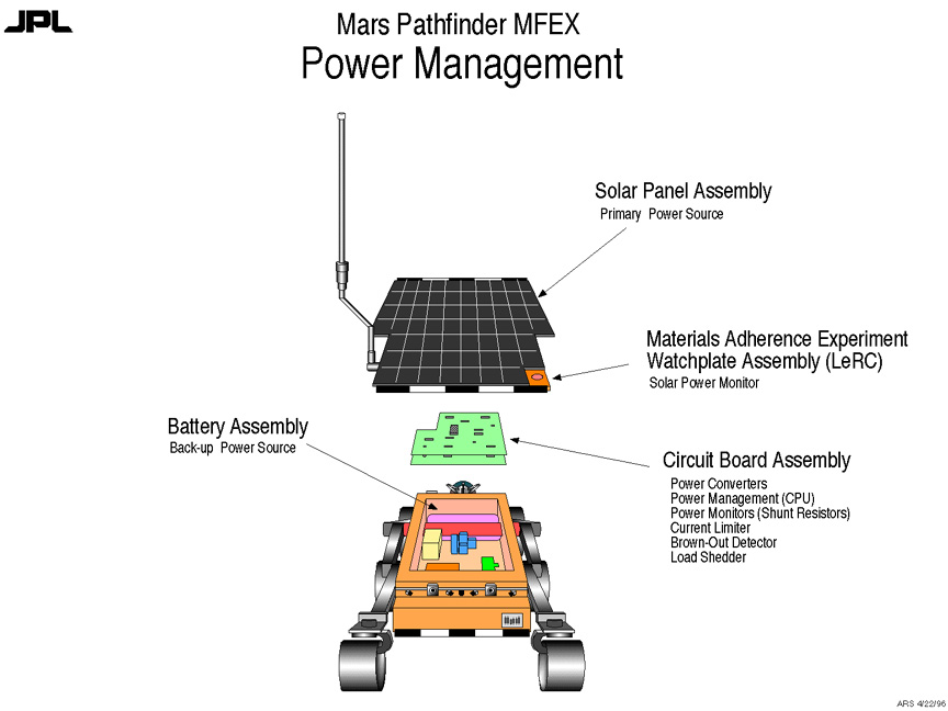
- Rover power hardware elements
- Primary power from GaAs solar panel
- Backup power from non-rechargeable LiSiCl2 batteries
- Primary mission objectives can be achieved if either (but not both!) power source is lost on landing
- Only one of three batteries on-line until landing to prevent inadvertent battery drain, and maintain passivation layers
-
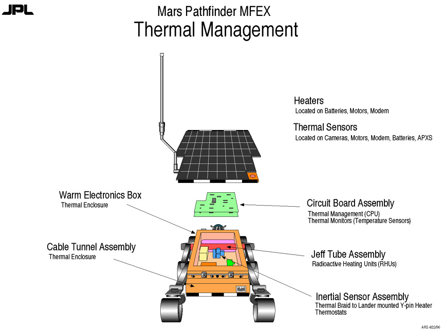
- Rover thermal hardware elements
- Internal electronics and batteries must remain in -40 degrees C to +40 degrees C (flight allowable) range
- Warm Electronics Box (WEB) is actively heated during the day, cools overnight
- Excess solar energy used to heat WEB to maximum allowable temperature
- Thermal management process run between command executions or every 10 seconds when rover is idle
- Heaters on batteries, modem, motors
-
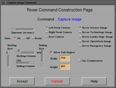
Imaging
- 2 front B&W cameras used in conjunction with laser stripe projectors for hazard detection; also provide imaging
- 1 rear color camera (rotated 90 degrees) used for imaging of APXS target area, rover tracks, and terrain
- "Cameras" are CCDs clocked out by rover CPU
- Auto-exposure capability
- 4.9 to 1 BTC data compression available for B&W images (causes loss of color information if used with rear camera)
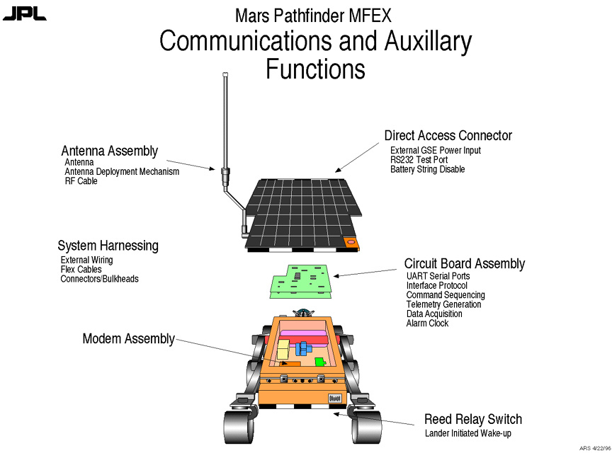
- Rover communications hardware elements
- Rover is the link master in half-duplex link (i.e., rover initiates all communications cycles)
- Lander listens all day
- Rover checks for sequence aborts before executing any command, and periodically when idle
- Rover attempts several communications retries, if necessary, before buffering telemetry
- Communications protocol uses error detection with retries (no error correction)
Telemetry
- Rover attempts to send telemetry at the completion of each command in a sequence
- Telemetry buffered to RAM or EEPROM if lander not available (LIFO)
- Buffered telemetry transmitted to lander at first opportunity
Mission phases
- Rover mission phases are:
- prelaunch
- cruise
- prerelease
- predeploy
- primary
- extended
- Mission phase transitions governed by rover sensor information (e.g., accelerometer readings), current phase, and command
- Phase used primarily to restrict rover actions (i.e., no use of actuators until rover has been released by the lander)
- Also determines which contingency sequence to trigger, if needed
-
Alpha Proton X-ray Spectrometer (APXS)
- determines elemental composition of rocks and soil
- requires deployment of sensor head against rock or soil surface
- data integration times up to 10 hours
- APXS can be powered while rover is shut down
- Rover cannot power both APXS and communications at once, but APXS needs significant periods of uninterrupted data collection
- APXS operation while rover executes other commands necessitates temporary disabling of rover communications
Material Adherence Experiment (MAE)
- Provides measure of dust deposition on rover solar panel during surface mission
- Clear glass dust cover operated using nitinol actuator; change in shorted solar cell current between open and closed dust cover states provides measure of transmittance of cover
- Quartz Crystal Monitor (QCM): differential frequency of QCM changes as mass of material deposited on it increases
Wheel Abrasion Experiment (WAE)
- Abradable materials bonded to center wheel
- During surface mission, material on wheel is worn away
- Photocell is mounted above wheel
- Change in reflectivity of segments of wheel provide measure of degree of abrasion
Other Technology Experiments:
- Terrain characterization
- Basic soil mechanics
- Sinkage
- Thermal characterization
- UHF link effectiveness
- Vehicle performance
- Dead reckoning and path reconstruction
- Vision sensor performance
Mission Experiments:
- Imaging of lander
- Lander damage assessment
-
Autonomous navigation requirement:
Due to communications constraints (light time delay, limited bandwidth, infrequent opportunities) and the need to respond in real-time to uncertain terrain conditions, the rover must be capable of autonomous navigation and hazard avoidance.
Waypoint Traverse
- Rover traverses to waypoints specified by human operator
- Capability to reach desired target dependent on highly accurate designation of waypoints in IMP stereo images
- Navigation occurs in the Surface Fixed Frame
- Rover deviates from straight-line path between waypoints in response to detected hazards (rocks, drop-offs, excessive tilt, etc.)
- Reflex-based control has no memory; no true onboard path planning
- Rate gyro and odometry support dead reckoning
- Daily updates of rover position/orientation provided from the ground based on analysis of IMP images, minimizing error accumulation
Laser hazard detection system detects rocks, drop-offs, and slopes
- Rover stops, captures image with selected lasers active
- Given "flat-earth" assumption, laser stripe will be visible in known position on CCD scanline
- Hazards cause laser stripe to slide along scanline (e.g., rock) or disappear (drop-off)
- Repeating process with 5 lasers generates sparse "map" of ground in front of rover (5 x 5 grid of elevation points)
- Hazard thresholds are empirically determined
- Not a stereo imaging system
Navigation safety features:
- Heartbeat: the rover stops periodically and confirms contact with lander before continuing traverse; if communications fails, rover retreats short distance and attempts to reestablish contact
- Lander avoidance: origin of navigation coordinate frame (lander position) is treated as a hazard, and avoided if necessary
- Bumper contact sensors: Any obstacle which somehow eluded the laser hazard detection system will, in the worst case, trigger the bumper contact sensors, aborting the traverse
- If waypoint destination is not reached by the time the command times out, remaining traverse is aborted
Other traverse capabilities:
- Find rock: Use hazard detection to approach an obstacle, rather than avoid it. Capability can be used to zero-in on APXS target rock.
- Move: Drives rover without servoing or active hazard detection
Command Loss (Earth/Lander Link)
- Backup command sequence load stored on lander
- Lander releases sequences to rover buffer in coordination with lander sequence execution
- Rover executes sequences nominally, "unaware" of contingency situation
- Approach allows for continued rover/lander activity coordination
Rover/Lander Communications Link Failure
- Rover transitions to contingency mission TBD hours after last successful receipt of command sequence upload
- Appropriate on-board contingency sequence triggered, depending on rover mission phase when contingency state began
- Rover assumes lander is still listening, sends telemetry without requiring ACK from lander
- Any rover telemetry received by lander during rover contingency mission is sent to Earth as "unrecognized rover packets"
- Rover continues to check for lander response, reverts to standard operation when command sequence received from lander
Rover EEPROM corruption
- Corrupted software will trigger "Rover Lite" command subset
- Rover Lite resident in rad hard PROM only
- Rover functionality limited in Rover Lite mode; ~50% of usual rover commands available
- Allows for recovering via patching of new rover software load
Device failures
- Failure counters on all (80) devices used to assess device states
- Failed sensors not used during rover operations
- Counters decrement if device becomes operational
- Devices can be forced "good" or "failed" by ground command
Some onboard functional redundancy
- accelerometers
- use of steering potentiometers in place of gyro
- etc.
-
-
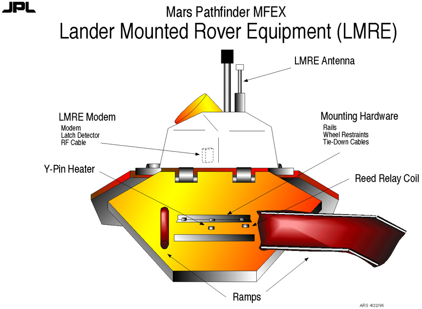
LMRE modem
- provides lander side of rover/lander communications link
- includes latchup detection/recovery circuitry
- heater available to keep modem in operating temperature range
LMRE antenna
Rover mounting hardware
- Rails to guide rover egress
- Restraints and tie-down cables to fix stowed rover to petal
Y-pin heater
- Compensates for heat loss from rover through "coldfinger" heater after landing
Ramps
RCW hardware:
- Silicon Graphics Crimson Reality Engine
- 128 Mb Ram
- 3 Gb disk
- Spaceball 6-DOF input device
- LCD shuttered goggles for stereo display
- Second identical control station available as hot backup
RCW software development environment:
- C++
- Open Inventor
- Open GL
- Builder Xcessory
- Tools.h++
- Motif 1.2.3
Custom software implementing RCW features
Interfaces
- to GDS for uplink
- to MIPL for IMP/rover images
RCW features:
- Graphical user interface for building rover command sequences

- Integrated stereo display and graphics overlays for designation of rover navigation waypoints
- 3D rover overlay for daily rover position updates

- Constraint checking to prevent input of out-of-range values
RCW inputs:
- Rover Planning/Assessment Reports (RPR and RAR)
- IMP image pairs provided by MIPL
- Camera models associated with each image pair
RCW outputs:
- Rover Activity Sequence File (RASF): Command sequence sent to rover
- Rover Activity Inspection Report (RAIF): File of comments to be inserted into SOE documents
- Rover Assessment Report (RAR): Human-readable version of rover command sequence
General rover telemetry processing not performed on RCW
- Packet processing handled by Pathfinder GDS
- Telemetry display on standard GDS workstations using DMD
- Rover team provides DMD display definitions to GDS
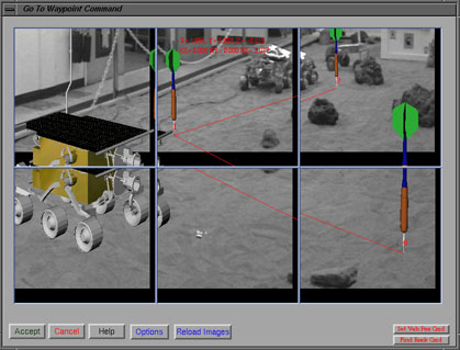
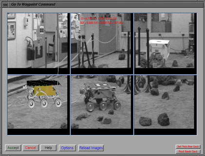
Waypoint Designation: Human operator places 3D cursor at the desired location in the stereo-rendered scene
- Accurate waypoint designation requires a CAHV model of each camera, and knowledge of the alignment of the two cameras to each other
- By selecting a waypoint in stereo, the operator effectively specifies that a pixel in the left camera view corresponds to the same location in the terrain as a particular pixel in the right camera view
- Accurate camera models ensure that the computed location of a selected feature in the image pair corresponds well to its position on the surface of Mars
- Camera models must be transformed as camera pointing changes (i.e., IMP pans/tilts)
- Given the IMP's 1 mradian resolution, and the human operator's ability to designate to a fraction (~1/10) of a pixel, designations to within ~6 cm at 10 meters range are achievable
Rover-related IMP Performance Issues
- Successful designation assumes that IMP camera alignment and calibrations will not change
- Camera toe-in for the IMP is effectively different for different filter sets; filter 5 is set of choice for rover ops
- Errors in IMP pointing knowledge translate directly into designation errors (i.e., ~1 degree azimuth backlash uncertainty is equivalent to
~25 cm cross-range error at 10 meters range)
- Can compensate for error if rover and target location both lie within the same image pair (relative designation then possible)
- Image registration by MIPL can also eliminate relative uncertainty in pointing between images in a panorama of IMP images, allowing for accurate designation across multiple image pairs; this may take more time to process than is available on some sols
Initial Conditions:
- Rover release pyros have been fired
- Ramps have been released
- Rover state is nominal
Sequence of activities:
- unstow rover
- drive down forward ramp onto surface
- navigate to first waypoint
- capture image of lander with color camera
- perform MAE experiment
- deploy APXS for soil data collection
- capture rover operations images with forward cameras
- collect APXS data for 1 hour
- shutdown rover, but continue to collect APXS data overnight
- awaken rover periodically overnight for health checks and transfer of APXS data
- Set alarm clock to awaken rover at 8am local time in case solar wakeup fails
RASF
- submitted for uplink processing
- A complete rover command sequence is viewed by Seqgen/Seqtran as the hex data field of a single ROVR_SEQNCE_LOAD command in the RASF
- Seqgen performs no validation of rover command sequence itself
- Seqgen does confirm that the rover sequence ID is a valid value given the NORMAL or EEPROM designation of the rover load
RAIF
- submitted for uplink processing
- contains only comments associated with the rover commands in its associated RASF
- Seqgen integrates RAIF comments into PEF file for inclusion in SOE
RAR (Rover Assessment Report)
- will be output in SOE editor format for convenient viewing
- RPR (Rover Planning Report) is an Excel version of the RAR generated using custom application, independent of RCW

NORMAL rover sequences
- stored in RAM after receipt, not released into the lander's rover buffer
- sequences identified by sequence ID between 1 and 32766
- requires execution of lander command QUEUE_ROVER_LOAD with correct sequence ID to make sequence available to rover
- deleted automatically after transmitted to rover
EEPROM rover sequences
- stored in EEPROM, not released to buffer
- sequences identified by sequence ID between 32767 and 65535
- requires execution of lander command QUEUE_ROVER_LOAD with correct sequence ID to make sequence available to rover
- remain stored in EEPROM until explicitly deleted by lander command
- may be reused (e.g., as part of Backup Mission Load)
Appropriate rover-related lander commands must be included in associated lander upload
- LMRE modem power must be on
- modem should be power cycled periodically for latchup protection
- IMP imaging commands necessary for updating rover position and generation of rover planning panorama
- DPT table must include sufficient priority for rover telemetry
Rover queries lander for new command sequence before executing next command in its currently active sequence
- usually no sequence is available (nominally, expect to uplink one rover command sequence per sol)
- if sequence is available, rover requests first frame
- if first command is not "abort sequence" then rover cancels the communications session, leaving the new sequence on the lander
- if first command is "abort sequence" then rover flushes its current command queue, and requests the rest of the new sequence
Rover can process only one sequence at a time
Rover performs sequence validation
- CRC evaluated as sequence is loaded
- individual commands validated before execution (e.g., number of parameters, range of parameter values)
- check is performed to determine if sufficient power is available to execute command
Lander Processing of Rover Telemetry
- Rover packets placed into APID queues in same way as lander-generated packets
- Rover telemetry is sorted into 12 APIDs
- Lander has no visibility into telemetry data, except for header information
Ground Processing of Rover Telemetry
- GDS performs super commutation of rover packets (thanks!)
- Rover telemetry will be fully integrated with Mars Pathfinder DMD system; rover engineering channels will be displayed as R-xxxx channels in a DMD "room" on any GDS workstation
Rover Operations Team
- Builds rover command sequences
- Requests IMP imagery from IMP team
- Interfaces with Experiment Team, Flight Engineers
Rover Engineering Team
- Evaluates rover engineering telemetry
- Determines rover state
- Develops recovery stategies
- Interfaces primarily with rover ops team
Rover Experiment Team
- Represents rover technology experiments
- Acts as part of overall experiment team
- Interfaces with rover ops team and rover engineering team
Web page author: Andrew.H.Mishkin
All information on this site, including text and images describing the Rover, is copyright © 1996, Jet Propulsion Laboratory, California Institute of Technology and the National Aeronautics and Space Administration.