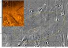
 Mars Pathfinder bounced down and rolled to a stop on the surface of
Mars on July 4, 1997. It landed in an ancient floodplain in the Ares
Vallis region of Chryse Planitia at 19.17 degrees North latitude, and
33.21 degrees West longitude. (The color inset in the image at right
shows the Chryse Planitia region of Mars. The mosaic is of the Ares
Vallis, with the position of the lander marked by a blue "X".)
Mars Pathfinder bounced down and rolled to a stop on the surface of
Mars on July 4, 1997. It landed in an ancient floodplain in the Ares
Vallis region of Chryse Planitia at 19.17 degrees North latitude, and
33.21 degrees West longitude. (The color inset in the image at right
shows the Chryse Planitia region of Mars. The mosaic is of the Ares
Vallis, with the position of the lander marked by a blue "X".) 16,661 images were collected by the Imager for Mars Pathfinder (IMP) camera. The IMP is a stereo camera with twelve filter positions. This permitted the imaging of the landscape surrounding the lander at a variety of wavelengths, lighting conditions, and resolutions. Most of the landscape was also imaged in stereo, allowing for the generation of a topographic map of the area around the lander.
A large portion of the image data was collected for a series of panoramas of the landscape. These panoramas differed from each other in terms of the coverage and compression of the data, the number of filters used, and whether they were stereo or monoscopic. Additional imaging was done to support various other investigations. Numerous images were taken of the Sun, Phobos and Deimos, a few stars, and the sky. Images were also taken of the Rover and the sites it investigated. Additional imaging targets included APXS investigation sites, the wind socks, and magnetic and radiometric calibration targets on the lander.
Landing Site
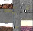 Several prominent features are visible around the landing site, which
are also visible in Viking Orbiter and Mars Global Surveyor images.
These include 'North Knob' 1.7 km to the north of the lander,
'Southeast Knob' 21.2 km to the southeast, 'Big Crater' 2.2 km to the
southeast, 'Far Knob' 30.6 km to the south, and the 'Twin Peaks' 0.86
km (North Twin) and 1.0 km (South Twin) to the west.
Several prominent features are visible around the landing site, which
are also visible in Viking Orbiter and Mars Global Surveyor images.
These include 'North Knob' 1.7 km to the north of the lander,
'Southeast Knob' 21.2 km to the southeast, 'Big Crater' 2.2 km to the
southeast, 'Far Knob' 30.6 km to the south, and the 'Twin Peaks' 0.86
km (North Twin) and 1.0 km (South Twin) to the west.
Using these features, the landing site has been pinpointed at 19.17 degrees north and 33.21 degrees west relative to the U.S. Geological Survey cartographic network. However, two-way ranging and Doppler tracking of the lander place the site at 19.30 degrees north and 33.52 degrees west in inertial space, suggesting that the USGS grid may be displaced about 19 km to the north and 7 km to the west.
In addition to the above features, other small craters are visible in the orbiter and lander views. 'Little Crater' and 'Rimshot Crater' (later identified as four small craters, A through D), all lie on the northwest outer flank of the rim of Big Crater. The azimuthal directions of these features from the landing site are shown below.
| Feature Name | Azimuthal Direction (in degrees E of N) |
|---|---|
| North Knob | 1 - 8 |
| Little Crater (crest) | 102 - 112 |
| Southeast Knob | 133 |
| Big Crater (rimcrest only) | 138 - 159 |
| Rimshot Crater A | 156 |
| Rimshot Crater B | 153 |
| Rimshot Crater C | 158 |
| Rimshot Crater D | 150 |
| Far Knob | 176 - 180 |
| South Twin | 242 |
| North Twin | 260 |
The lander is on the southeast-facing flank of a low ridge, giving the overall landing site (out to about 50-100 meters) a slight slope of two or three degrees, dipping to the southeast. Very distant features to the south and east are in view, whereas relatively nearby features to the north are partially or completely obscured. Only the tip of North Knob, which appears larger in the Viking orbiter images than the Twin Peaks, projects above the local horizon. A 300 m crater, 1.2 km to the northeast, is completely obscured.
The radius of Mars at the landing site is 3,389.714 km.
Processing
Prior to retrieval of the data on the ground, a number of processing
steps were executed onboard the spacecraft, primarily with the intent
of cleaning up the data in preparation for compression. They include
'shutter effect' correction, dark current subtraction, flat fielding,
bad pixel correction, and sub-framing as necessary. (Although the
flat fielding capability existed, it was never actually used.)
Compression is also a part of onboard processing, but it will be
discussed in the section titled 'Data Compression'.
The onboard data processing stream begins by dropping the anti-blooming gates to clear charge in the imaging area of the 512 square CCD, which comprises only the upper 256 rows. Designed for stereo imaging, the first 256 columns in the imaging area correspond to the left image and the second 256 columns are reserved for the right image. Exposure begins when the anti-blooming gates are raised and electrons begin to accumulate in the pixel charge wells. At the end of the set exposure time, the image is shifted row by row to the lower 256 rows in the CCD that make up the storage area, taking less than 0.5 milliseconds. During this time additional electrons build up in the active area, causing the last row transferred to have a longer exposure than the first. The DN's are then read out to the frame buffer board, which takes about 1.25 seconds, and digitized to 12 bits. Optionally, a zero-exposed frame can be subtracted at this point. One complete set of left and right IMP images can remain in the frame buffer board long enough to be read by the onboard computer into main memory. This frame transfer capability of the CCD avoids the need for a mechanical shutter by effectively working as an electronic shutter. The complete transfer time is referred to as the 'shutter effect'.
 Note that the flight software is capable of reading out each 256x256
storage area, but border effects were minimized by ignoring the top
two lines and bottom six lines, yielding a nominal image area of 248
lines by 256 samples.
Note that the flight software is capable of reading out each 256x256
storage area, but border effects were minimized by ignoring the top
two lines and bottom six lines, yielding a nominal image area of 248
lines by 256 samples.
Additional CCD features include 4 'null' pixels in the readout register, an 8-pixel wide covered dark strip, and a 2-pixel wide border on each edge of the CCD. They provide for the generation of 4 calibration images that can be used for the calibration of each IMP scene. These are the zero-exposure image, dark current, zero-exposure dark current, and flat field. Only the actual scene exposed image is required for scene correction, since the other images can be generated based on previous exposures.
The dark current is the sum of currents produced in the CCD imaging section, the storage section, and the serial readout register, added to the hardware offset. It is an exponential function of temperature and a linear function of integration time. A small light leak into the 8-pixel wide dark strip required modification to the onboard algorithm so that it could be used to scale dark current corrections in later images.
A flat field image attempts to model the responsivity variation across the CCD field-of-view, and is a function of wavelength. Because of onboard memory constraints, only one flat fielding correction table was permitted, and was comprised of the average of the tables for spectral filters 5 through 11 (excluding the diopter filter in the right eye). This limits onboard flat field corrections to only filters from which the average was computed. Optimum correction is also limited by the scene noise and the accuracy with which the responsivity variation is known.
Bad pixels fall into three categories: hot strip (have higher than average dark current but fail the variability or linearity test), high variability (highly fluctuating dark currents, or fail linearity test), and vignetted pixels (severe vignetting causes order of magnitude higher variability). Their locations are identified in a bad pixel map for corrective application. Filter 0 turned out to be the most critical for bad pixel detection.
Key onboard processes were flagged, and they include the following:
The IMP Experiment Data Records were created at the Multimission Image Processing Laboratory of the Jet Propulsion Laboratory.
Data Compression
Because the IMP can generate data at a much higher rate than can be
downlinked, various compression techniques were used, depending on the
nature of the image data. Lossless compression used the JPL-developed
Rice algorithm. For lossy compression during non-science or low data
rate scenarios, a modified JPEG compressor developed at the Technical
University of Braunschweig was used. Nominally, JPEG compression
involves a discrete cosine transform (DCT), but can be enhanced by a
local cosine transform (LCT). Note that the instrument compression
block size for JPEG compression was 8x8, and was variable for RICE
compression.
For the JPEG compression, there are two types of entropy encoding: Huffman and arithmetic. In the Mars Pathfinder scenario, the possibility of transmission errors using 'adaptive' Huffman coding (in which the coding table is adapted to data statistics and transmitted to the ground) required instead the use of a 'fixed' Huffman table. On the other hand, the arithmetic encoder scheme did not require a table, as it adapted to the input data on-the-fly while using a state machine for probability estimation on both the encoder and decoder side.
The JPEG compression was operated via one of two user specified criteria: Quality and Ratio. Specifying a Quality value targets a desired level of image quality which the compression must satisfy. The lower the selected Quality, the higher the gain in compression factor. Use of the second type of criteria, a Ratio, was more straightforward in that it defined the compression factor a priori.
On the first Sol, lossy JPEG compression enabled the downlink and assembly of a full 360 degree, 670 nm filter panorama halfway through Sol 1 operations. The compression rates fell steadily after the first week of operation as downlink rates increased above the expected rates.
The valid Compression Types are listed below:
| Compression Type | Encoding | User Specified Criteria | |
|---|---|---|---|
| #1 | JPEG Discrete Cosine Transform (DCT) | HUFFMAN | QUALITY |
| #2 | JPEG Discrete Cosine Transform (DCT) | HUFFMAN | RATIO |
| #3 | JPEG Discrete Cosine Transform (DCT) | ARITHMETIC | QUALITY |
| #4 | JPEG Discrete Cosine Transform (DCT) | ARITHMETIC | RATIO |
| #5 | JPEG Discrete Cosine Transform (DCT) | HUFFMAN | QUALITY (LCT) |
| #6 | JPEG Discrete Cosine Transform (DCT) | HUFFMAN | RATIO (LCT) |
| #7 | JPEG Discrete Cosine Transform (DCT) | ARITHMETIC | QUALITY (LCT) |
| #8 | JPEG Discrete Cosine Transform (DCT) | ARITHMETIC | RATIO (LCT) |
| #9 | RICE Adaptive Variable-length Coding | - | - |
The number of completed IMP images by Compression Type are listed below:
| Compression Type |
Number of Completed Images |
Average Compression Ratio Per Image |
Average Compression Rate Per Image |
|---|---|---|---|
| none | 2296 | - | - |
| #1 | 6 | 25.02 | 0.4871 |
| #2 | 2842 | 62.74 | 0.3200 |
| #3 | 358 | 289.99 | 0.4632 |
| #4 | 552 | 42.57 | 0.3483 |
| #5 | (not used) | - | - |
| #6 | (not used) | - | - |
| #7 | 46 | 5873.07 | 0.0022 |
| #8 | 7262 | 10.15 | 2.8662 |
| #9 | 3544 | 1.56 | 9.0938 |
| TOTAL | 16661 | 45.58 | 3.6258 |
NOTE: The ratio multiplied by the rate is not exactly 12 (bits) because the numbers in the table are averaged over the number of images and not the total number of bits.
The instrument JPEG compression quantization table, listed in 'zigzag' order, is shown below:
| 16 | 11 | 12 | 14 | 12 | 10 | 16 | 14 |
| 13 | 14 | 18 | 17 | 16 | 19 | 24 | 40 |
| 26 | 24 | 22 | 22 | 24 | 49 | 35 | 37 |
| 29 | 40 | 58 | 51 | 61 | 60 | 57 | 51 |
| 56 | 55 | 64 | 72 | 92 | 78 | 64 | 68 |
| 87 | 69 | 55 | 56 | 80 | 109 | 81 | 87 |
| 95 | 98 | 103 | 104 | 103 | 62 | 77 | 113 |
| 121 | 112 | 100 | 120 | 92 | 101 | 103 | 99 |
Other methods of conserving downlink resources included sub-framing the image, row and column sums, and pixel averaging (in addition to JPEG), all of which were useful for atmospheric science images. For highest compression, these methods were used in combination with each other.
Sub-framing was used in returning 31x31 pixel blocks of the Sun. (A subcategory of these images were the so-called 'ATMOS FLAG' images. They are distinct from the regular Sun images in that the location of the Sun was determined automatically on-board the spacecraft. The position of these ATMOS FLAG sub-frames within the CCD array was not returned to the ground.)
Row and column sums were used for sky images, as they gave the gradient and the edges of cloud features, but not the high resolution of an image.
Pixel averaging was sometimes done prior to data compression. This involved replacing each 'block' of pixels in an image by the average of the pixels in that block. The size of the block or area over which the averaging was done was defined in the horizontal or sample direction by the pixel_averaging_width, and over the vertical or line direction by the pixel_averaging_height. Rectangular blocks were permitted. Although the pixel averaging technique reduces the spatial resolution of an image, the color information was largely retained and was overlaid onto higher resolution monochrome images for 'first look' color characterization.
Data
A variety of types of data were returned, and as mentioned in the
'Compression' section, were submitted to lower and lower compression
rates as downlink rates increased above the expected rates.
Eventually, large sets of image data were returned lossless,
contributing to a 'hi-res' panorama called the Superpan.
This table from the 'End of Mission Report' provides a detailed correlation between data type and compression rates. The items in the Description column are shown in the format exxx(comp,pa)=n, where e=(R)ight or (L)eft eye, xxx = wavelength (nm), comp = compression ratio, pa = pixel averaging size, and n = number of images. 'q' = quality factor and 'los' = lossless (Rice) compression. Only regular images are included in the table; dark strips, null strips, and dark current images are excluded.
| Observation | Description | Number of Images | Observation Time |
|---|---|---|---|
| First Look (Mission Success) Panorama |
R440(12:1,2x2)=32 R670(24:1,1x1)=19 RL670(12:1,1x1)=26 R670(80:1,1x1)=15 R530(12:1,2x2)=32 R440(q=09,2x2)=07 R670(q=15,1x1)=07 R530(q=09,2x2)=07 |
145 | Sol 1 Morning |
| Predeploy Red/IR Panorama |
R670(12:1,1x1)=30 R670(q=15,1x1)=20 R965(6:1,1x1)=89 |
139 | Sol 1 Morning |
| Insurance Panorama |
RL440(los,1x1)=168 R530(los,1x1)=84 R600(los,1x1)=84 R750(los,1x1)=84 |
420 | Sol 2 Afternoon |
| Monster Panorama |
R440(6:1,2x2)=50 R530(6:1,2x2)=50 RL670(6:1,1x1)=195 R750(6:1,2x2)=50 R965(6:1,2x2)=50 |
395 | Sol 3 Various |
| Presidential (Gallery) Panorama |
R440(q=65,1x1)=33 R440(6:1,1x1)=132 R530(q=65,1x1)=33 R530(6:1,1x1)=132 R670(q=65,1x1)=33 R670(6:1,1x1)=132 |
4951 | Sol 9, 10, 11 Morning |
| Super Panorama |
RL440(los,1x1)=2382 R480(2:1,1x1)=119 R530(2:1,1x1)=119 R600(2:1,1x1)=119 RL670(los,1x1)=238 R750(2:1,1x1)=119 L800(2:1,1x1)=119 L860(2:1,1x1)=119 L900(2:1,1x1)=119 L930(2:1,1x1)=119 RL965(2:1,1x1)=238 L1000(2:1,1x1)=119 |
17853 | Various |
| 1 | excludes 22 duplicate images from two aborted sequence 164 runs |
| 2 | compression in RL440 began as 2:1 JPEG and was later changed to lossless during acquisition |
| 3 | includes only complete cubes |
The returned data types are listed as follows:
| Image Type | Image Size (lines x samples) |
Pixel Size (bits) |
Description |
|---|---|---|---|
| Image Data | 248 x 256 | 12 | Image data is unsigned and archived top side up. Right images have been rotated counter-clockwise; left images have been rotated clockwise. |
| Dark Strip | 248 x 8 | 12 | Calibration data retrieved from covered area of the CCD. |
| Null Strip | 248 x 4 | 12 | Calibration data retrieved from the readout register of the CCD. |
| Flat Field | 248 x 256 | 12 | Flat Field data is unsigned and archived top side up. Right images have been rotated counter-clockwise, left images have been rotated clockwise. |
| Dark Frame | 248 x 256 | 12 | Dark Frame data is unsigned and archived top side up. Right images have been rotated counter-clockwise, left images have been rotated clockwise. |
NOTE: Two additional data types, 'Histogram' images and 'Summed' images, were originally included as possible data types. However, since no images with these data types were returned, they have not been described here.
Coordinate Systems
and Image Geometry
Of the many coordinate systems defined by the Mars Pathfinder Project,
four are of particular interest in understanding the IMP data. These
are the Mars Pathfinder Lander Coordinate Frame (L Frame), the IMP
Coordinate Frame (IMP Frame), the Martian Local Level Coordinate Frame
(M Frame), and the Mars Surface Fixed Coordinate Frame (MFX
Frame).
The Mars Pathfinder Lander (L) Coordinate Frame
 The Mars Pathfinder Lander is a tetrahedral structure. One of its
faces, the one upon which it sits, is called the base petal and houses
most of the lander equipment. The other three faces, or petals, open
after surface impact to expose these systems. The rover is mounted on
one of these petals. The Mars Pathfinder Lander Coordinate Frame, or
'L' Frame, has the lander base petal as its reference plane and its
center coincident with the geometric center of the base petal. The
YL-axis of this coordinate system passes through the
geometric center of the rover petal, and defines the reference
direction. The ZL-axis is normal to the reference plane
and coincident with the nominal spacecraft spin vector. When the
lander is upright on the surface, the ZL-axis is directed
positively downward into the ground.
The Mars Pathfinder Lander is a tetrahedral structure. One of its
faces, the one upon which it sits, is called the base petal and houses
most of the lander equipment. The other three faces, or petals, open
after surface impact to expose these systems. The rover is mounted on
one of these petals. The Mars Pathfinder Lander Coordinate Frame, or
'L' Frame, has the lander base petal as its reference plane and its
center coincident with the geometric center of the base petal. The
YL-axis of this coordinate system passes through the
geometric center of the rover petal, and defines the reference
direction. The ZL-axis is normal to the reference plane
and coincident with the nominal spacecraft spin vector. When the
lander is upright on the surface, the ZL-axis is directed
positively downward into the ground.
 The IMP Coordinate Frame
The IMP Coordinate Frame is co-linear with the Mars Pathfinder Lander Coordinate Frame. However, its origin is offset, and is located at (-198.4, -9.0, -436.7) mm with respect to the origin of the L Frame. The XIMP-YIMP plane is defined as the interface plane between the lander structure and the IMP camera base.
The Martian Local Level (M) Coordinate Frame
The Martian Local Level Coordinate Frame is a right handed, orthogonal, frame whose origin is co-incident with the origin of the Lander Coordinate Frame. The XM axis points north, the YM axis points east, and the ZM axis points down. This sytem is defined relative to the Mars areocentric coordinate system.
The Mars Surface Fixed (MFX) Coordinate Frame
This coordinate frame is defined as being initially equivalent to the Martian Local Level Coordinate Frame. While the origin of the Local Level frame shifts with the origin of the Lander Coordinate Frame as the lander itself settles and shifts, the origin of the Mars Surface Fixed Coordinate Frame becomes fixed once the initial orientation and position of the lander has been determined. However, in practice, the position of the lander changed so little after the determination of the origin of the MFX frame, that it essentially remained equivalent to the M Frame throughout the mission.
Other coordinate systems were under discussion at the time this archive was assembled and may be used for future data releases.
The Lander-Surface quaternion defining the conversion between the Lander Coordinate Frame and the Mars Surface Fixed frame was determined four times during the mission. The greatest change occurred between the first and second determinations, during which time the rover petal and airbags were repositioned.
The following table shows the four values of the quaternion listed in the NAIF defined order of 'cosine, x, y, z'. (MIPL determinations of camera pointing for images in this archive were done using only the first two quaternions.) Also shown in this table is the direction of North, the tilt of the lander, and the azimuth of the lander tilt, all measured with respect to the Lander Coordinate Frame.
| # | SCLK | cosine | x | y | z | North (deg) |
Tilt (deg) |
TiltAz (deg) |
|---|---|---|---|---|---|---|---|---|
| 1 | 1246747789* | 0.2100 | -0.0169 | -0.0169 | 0.9774 | 155.75 | 2.74 | 147.12 |
| 2 | 1246761006 | 0.2102 | -0.0146 | -0.0293 | 0.9771 | 155.75 | 3.75 | 165.65 |
| 3 | 1247191866 | 0.2102 | -0.0148 | -0.0317 | 0.9770 | 155.71 | 4.01 | 167.09 |
| 4 | 1248364781 | 0.2102 | -0.0149 | -0.0333 | 0.9770 | 155.71 | 4.18 | 168.09 |
*The first SCLK value listed was chosen as ten seconds before the first image was acquired.
Azimuth and Elevation Determination
Contrary to the nadir-pointing Z axes of the above coordinate systems, measurements of elevation for camera pointing and solar position in this IMP EDR archive were measured positively upwards from their horizontal reference planes, in order to be consistent with common usage in planetary science and astronomy. This change has been emphasized with the use of the POSITIVE_ELEVATION_DIRECTION = UP keyword in the PDS labels.
At the time this CD archive was created, three well-established methods were available for generating instrument azimuth and elevation values (ie., those measured with respect to the lander coordinate frame) from the azimuth and elevation motor clicks. (In the following discussion, azimuth and elevation refer to boresight or camera head pointing, as opposed to the pointing of the individual camera eyes.) These three methods were called the TELEMETRY, MPFNAV-MIPS, and BACKLASH-UOFA methods.
The method that was used for the images in this archive was that employed during the realtime processing, the TELEMETRY method, which used the following simple algorithms:
IMP stowed:
instrument_azimuth = (436 - azimuth_motor_clicks) * 0.5535
instrument_elevation = (elevation_motor_clicks - 173.86) * 0.5535
IMP deployed:
instrument_azimuth = (380 - azimuth_motor_clicks) * 0.5535
instrument_elevation = (elevation_motor_clicks - 173.86) * 0.5535
The MPFNAV-MIPS method uses the VICAR MPFNAV program which adjusts the commanded pointing values in a set of image labels until the images mosaic properly. MPFNAV performs the pointing adjustment by minimizing the discrepancy between a set of tiepoints measured across adjacent image borders and their predicted locations based upon a camera model. While this method provides more accurate pointing information by removing random pointing inaccuracies, it is more labor intensive than the TELEMETRY method, and had not been completed for most of the images at the time this archive was made.
The third method for determination of instrument pointing is the BACKLASH-UOFA method. This method is based on an attempt to characterize the backlash effect of the camera on image pointing. The University of Arizona has implemented an algorithm to attempt to compensate for this. For the most part, this produces accurate results. The only drawback is that all previous camera movements must be accurately known, which they aren't.
Both the lander surface quaternion and the instrument pointing are likely to undergo changes as improved values are determined in the future. The most up-to-date spacecraft and instrument kernels available can be obtained from the anonymous FTP site of the Navigation and Ancillary Information Facility at JPL, ftp://naif.jpl.nasa.gov/. For further assistance, contact Boris Semenov of the PDS NAIF node:
| Address: |
Boris Semenov M/S 301-150 Jet Propulsion Laboratory 4800 Oak Grove Drive Pasadena, CA 91109 |
| Phone: | (818) 354-8136 |
| Email: | Boris.V.Semenov@jpl.nasa.gov |
| WWW URL: | http://pds.jpl.nasa.gov/naif.html |
| FTP Site: | ftp://naif.jpl.nasa.gov/ |
Incidence, phase, and emission angles were not included for the images in this archive. This was primarily due to the difficulty of determining these values in a lander setting and the ambiguities that would be associated with any values provided. Due to the large field of view of the camera and the irregular feature surfaces and landscape variations, the emission angle (and therefore the phase angle) can vary significantly across an image scene. Instead, the position of the Sun at the time each image was acquired has been included in the solar azimuth and solar elevation keywords. From these, users can determine the local incidence, phase, and emission values that will be of particular interest to them.
For more information on Mars Pathfinder coordinate systems, see the [MELLSTROM&LAU1996], [WELLMAN1996B], and [VAUGHAN1995] references. The [WELLMAN1996B] document in particular provides good coverage of the coordinate systems related to the IMP camera. Please note that where he used elevation ranges of 0 to 180 degrees, the MPF Project used -90 to +90 degrees.
Calibration
In addition to the IMP camera calibration discussed in the IMP
instrument catalog object, there are a couple of calibration issues
relating to targets the camera imaged. Specifically, these are the
investigation of wind speed and direction through imaging of the wind
socks on the ASI/MET mast, and the magnetic properties investigation
performed by imaging the magnets mounted on the lander.
The calibration files and algorithms for these investigations are not yet completed. Calibration information for the IMP camera is available in [REIDETAL1998]; information about the magnetic properties experiment is available in [GUNNLAUGSSONETAL1998].
Software
The IMP EDR images can be displayed on UNIX, Macintosh, and PC
platforms using the PDS developed program, NASAView. This software is
freely available from the PDS Central Node and may be obtained from
their web site at http://pds.jpl.nasa.gov/. For more information or
help in obtaining the software, contact the PDS operator at the
following address:
| Address: |
Planetary Data System, PDS Operator Jet Propulsion Laboratory 4800 Oak Grove Drive Pasadena, CA 91109 |
| Phone: | (818) 354-4321 |
| Email: | pds_operator@jpl.nasa.gov |
| WWW URL: | http://pds.jpl.nasa.gov/ |
The real time processing of the VICAR-formatted IMP data was done using the VICAR suite of image processing programs. For information on obtaining VICAR, please contact:
| Address: |
Danika Jensen M/S 168-514 Jet Propulsion Laboratory 4800 Oak Grove Drive Pasadena, CA 91109 |
| Phone: | (818) 354-6269 |
| Email: | Danika.Jensen@jpl.nasa.gov |
| WWW URL: | http://www-mipl.jpl.nasa.gov/vicar.html (info about VICAR) |
Some IMP calibration and processing programs have been written in IDL (Interactive Data Language). IDL is available from Research Systems Incorporated at http://www.rsinc.com/.
Media / Format
The IMP EDR data will be stored on compact disc-read only memory
(CD-ROM) media. The CDs will be formatted according to ISO-9660 and
PDS standards. The data files will not include extended attribute
records (XARs), and will therefore not be readable on some older VMS
operating systems.
Confidence Level
Overview
The Imager for Mars Pathfinder (IMP) functioned flawlessly during the
83 sols of operation on the Martian surface. The IMP flight software,
the filter wheel, and the az/el motors functioned nominally. There
were no software or hardware problems during operations.
IMP command and sequence generation was dynamic and flexible. Command sequences were often generated in as little as one hour before the uplink window and typically required only 1-2 people to design, write, and run the sequence through the 'uplink shell'. This capability allowed the imaging team to respond rapidly to new situations (such as unexpected changes in the rover traverse path) and adjust accordingly.
The Application Packet ID (APID) architecture was well suited for imaging operations and data transmission. IMP images were assigned a priority (as part of the image command) and stored in a specific buffer (according to its priority) onboard the spacecraft. These buffers were downlinked accordingly, with the highest priority data downlinked first. If an image packet was 'lost' during downlink (i.e., not received at Earth), there existed a mechanism for retransmission from the spacecraft.
Review
Prior to release, the data will be reviewed by the IMP instrument team
and the Planetary Data System.
Data Coverage and
Quality
The first panorama (the Mission Success Pan and Predeploy red/IR Pan)
was well designed and served its intended purpose. The third
panorama, the Monster Pan, was designed for a lower downlink volume
mission and included only 2/4 tiers of color coverage. Stereo overlap
was incomplete between adjacent images. The 4th panorama, the
Gallery/Presidential Pan, was a 5-tier, 6:1 JPEG panorama (the
previous pans were 4 tiers) in 3 filters (440 nm, 530 nm, and 670 nm),
acquired over 3 days in a time-continuous fashion (495 images total).
The 5th and final panorama, the Superpan, was designed as a full (12
filter) spectral/stereo panorama (originally to include 2,160 image
frames) compressed losslessly in two filters (670 nm, 440 nm) and 2:1
JPEG in the other filters. A large number of R9 and R10 frames of the
sky were returned saturated (due to the incorrect use of the
autoexposure command). Although the superpan is only 83% 'complete',
it has returned a rich, multispectral data set.
For a detailed characterization of each panorama, see [GOLOMBEKETAL1998A].
The summary table for IMP Observations follows:
| Observation Description (by sequence) | Number of Images |
|---|---|
| Atmospheric (sun and sky) | 4,832 |
| Surface Panoramas | 3,774 |
| Windsocks | 1,812 |
| Rover Support | 1,479 |
| Astronomy | 1,136 |
| APXS sites, multispectral spots & slices | 992 |
| Magnetic Targets | 665 |
| Super resolution | 585 |
| Radiometric calibration targets | 567 |
| Photometric spots | 321 |
| Miscellaneous (dust devil search, change monitoring, deep field test, Yogi photometry, fiducial marks) | 252 |
| Dark frames, dark/null strips | 26 (cruise) 220 |
| TOTAL | 26 (cruise) 16635 (surface) 16,661 total images |
Limitations
For some of the panoramas, particularly the Insurance Pan and the
Monster Pan, the camera pointing was commanded such that very little
overlap between frames occurred in certain areas. The limited overlap
played havoc with the auto-correlation methods devised to
systematically generate mosaics within a very short time period. Time
consuming manual tiepointing of frames was required to yield results
reliable enough to support the Rover navigation operations, including
portions of the Monster Pan and the smaller 2 to 4-frame End-of-Day
mosaics. Improvements to the commanding of the camera pointing were
made by the time the Gallery/Presidential Pan was returned.
In the case of the voluminous multispectral Superpan, a large number of R9 and R10 filter frames of the sky were saturated (due to the incorrect use of the auto-exposure command). This preempted a true color rendition of the sky using Superpan data.
Regarding compression, the JPEG method inherently produced blocky artifacts.
Although APID architecture provided a mechanism for retransmission of 'missing' packets from the spacecraft, this was not perfected until the middle period of the mission. So, some image packets from the early period of the mission were not recovered.
Related Information
The following links provide some additional information about topics
related to this dataset. You must be connected to the Internet for
most of these links to work, since they are located on the web site of
the Central Node of the Planetary Data System.