ASI/MET data were collected during different phases of the mission by accelerometers and wind, temperature, and pressure sensors mounted in various places on the spacecraft.
Data acquired during the entry, descent, and landing (EDL) phase of the mission permitted the reconstruction of profiles of atmospheric density, temperature and pressure from altitudes in excess of 100 km to the surface. After the landing, day to day variations in temperature, pressure, and wind speed were monitored.
Combined with information collected from the Imager for Mars Pathfinder about atmospheric aerosols and dust, the amount of water vapor at the landing site, and wind information derived from observation of the MET mast-mounted wind socks, these data should contribute to a better understanding of the overall structure of the Martian atmosphere, and its variation over time. A further comparison with data collected by the Viking Lander spacecraft can also reveal information about the longer-term evolution of the atmosphere.
For more information about the scientific objectives of the ASI/MET investigation, please see [SEIFFETAL1997].
 All six science and engineering accelerometers are Allied Signal
QA-3000-003 units. The three science accelerometers are mutually
orthogonal and are oriented parallel to the lander X, Y, and Z axes,
whereas the three orthogonal engineering accelerometers are oriented
in the X direction and at ±45° to the Z-axis (+YZ and -YZ).
Because of limitations imposed by the Pathfinder system design, some
accelerometers are displaced significantly from the entry vehicle
center of mass.
All six science and engineering accelerometers are Allied Signal
QA-3000-003 units. The three science accelerometers are mutually
orthogonal and are oriented parallel to the lander X, Y, and Z axes,
whereas the three orthogonal engineering accelerometers are oriented
in the X direction and at ±45° to the Z-axis (+YZ and -YZ).
Because of limitations imposed by the Pathfinder system design, some
accelerometers are displaced significantly from the entry vehicle
center of mass. The primary function of the engineering accelerometers is to monitor and contribute to the timing of important events during entry and descent, such as parachute deployment. They are also used after landing to right the spacecraft and point the lander high gain antenna accurately. Science accelerometer observations focus on measuring atmospheric accelerations throughout entry and descent with maximum resolution, although the optimum measurement strategy has been modified to provide redundancy for the engineering accelerometers. Data from all six accelerometers are sampled at the same rate and will be available to ASI/MET investigators.
 Atmospheric temperatures during the descent and landed phases of the
mission are measured by fine wire chromel-constantan thermocouple
sensors mounted on the mast. It consists of three thermocouples wired
in parallel in a fiberglass support structure. The thermocouple wires
are 75 um in diameter and the junction diameter is approximately 200
um. The fine wires provide conductive isolation for the junctions,
and ensure that they reach equilibrium with the tenuous martian
atmosphere fairly rapidly, although radiative corrections will have to
be modeled to obtain the best results from these sensors. Three wires
provide redundancy against damage, either during descent, or due to
dust storms during the landed mission.
Atmospheric temperatures during the descent and landed phases of the
mission are measured by fine wire chromel-constantan thermocouple
sensors mounted on the mast. It consists of three thermocouples wired
in parallel in a fiberglass support structure. The thermocouple wires
are 75 um in diameter and the junction diameter is approximately 200
um. The fine wires provide conductive isolation for the junctions,
and ensure that they reach equilibrium with the tenuous martian
atmosphere fairly rapidly, although radiative corrections will have to
be modeled to obtain the best results from these sensors. Three wires
provide redundancy against damage, either during descent, or due to
dust storms during the landed mission. A single thermocouple is assigned to temperature measurements during the descent phase of the mission, when the entry vehicle is falling by parachute after the heat shield has been jettisoned. The descent sensor is located near the top of the mast, immediately below the wind sensor. Its thermocouple wires are approximately 4.0 cm from the mast axis and are oriented perpendicularly to it. During descent the mast is stowed and the sensor is close to the center of an aperture in the corner of the lander, although it is set back significantly due to concerns over interference with the lander airbags. Accurate descent temperature measurements rely on undisturbed air flowing through the aperture and over the descent sensor. Wind tunnel measurements on models have shown that this flow is highly disturbed, so that descent temperature measurements are likely to be unreliable. Currently a flexible duct linking the external flow to the sensor is planned to improve the quality of the data.
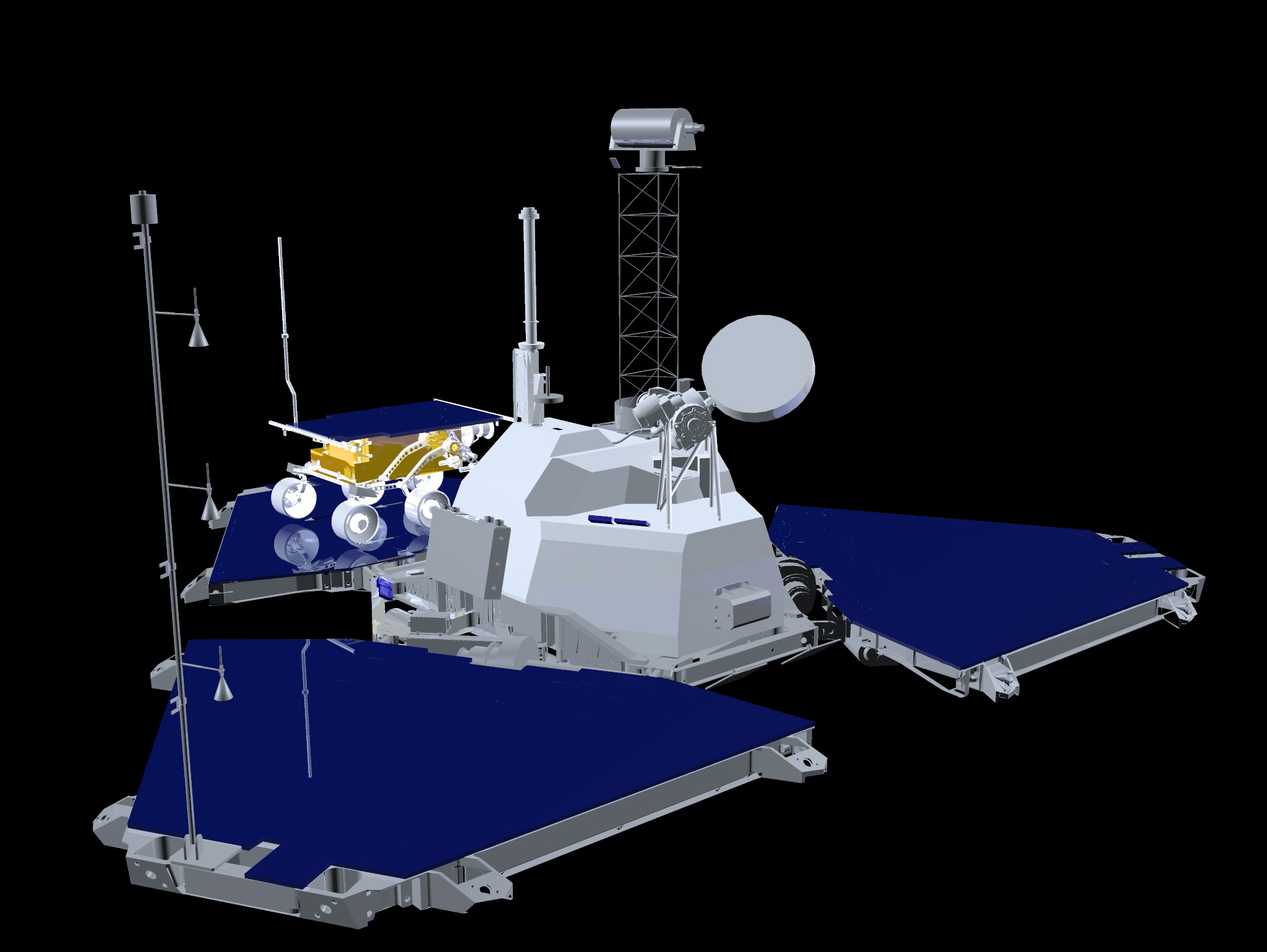
Three thermocouples are designed for temperature measurements during the landed phase of the mission when the mast is deployed. These sensors are located on the mast 0.273, 0.508 and 1.038 m above the plane of the petal. For each sensor, the thermocouple wires are oriented vertically approximately 2.6 cm from the mast axis. All three sensors and mounts are identical and are clocked at the same angle on the mast. Temperature measurements are subject to thermal contamination when the mast is downwind from the spacecraft or the sensor wires are downwind from the mast. The sensors are therefore oriented away from the spacecraft when the mast is deployed so that these conditions coincide, minimizing the range of unfavorable wind directions. The orientation on Mars is 130° east of north (pointing roughly southeast).
 ASI/MET uses hot wire resistance thermometers to measure wind speed
and direction. The sensor consists of six 50 um diameter platinum-
iridium wire elements arranged symmetrically around a cylindrical core
approximately 2.6 cm in diameter. Each element consists of a 20 cm
wire wound around insulating formers to give eight closely spaced
lengths oriented parallel to the axis of the mast roughly 3 mm from
the core. The sensor is mounted at the top of the mast, at a height
of 1.096 m above the lander petals. All six sensor elements are
connected in series and are heated by a constant current source. In
still air at typical martian surface pressures, the elements are
heated to approximately 40°C above ambient. Wind blowing round
the core of the sensor cools the elements, and the cooling produced at
an individual element depends on its position relative to the core and
the wind direction. Overall cooling is dependent on wind speed and
the pattern of cooling for the six elements is a indicator of wind
direction. Sensitivity is greatest for low winds and varies roughly
inversely with wind speed.
ASI/MET uses hot wire resistance thermometers to measure wind speed
and direction. The sensor consists of six 50 um diameter platinum-
iridium wire elements arranged symmetrically around a cylindrical core
approximately 2.6 cm in diameter. Each element consists of a 20 cm
wire wound around insulating formers to give eight closely spaced
lengths oriented parallel to the axis of the mast roughly 3 mm from
the core. The sensor is mounted at the top of the mast, at a height
of 1.096 m above the lander petals. All six sensor elements are
connected in series and are heated by a constant current source. In
still air at typical martian surface pressures, the elements are
heated to approximately 40°C above ambient. Wind blowing round
the core of the sensor cools the elements, and the cooling produced at
an individual element depends on its position relative to the core and
the wind direction. Overall cooling is dependent on wind speed and
the pattern of cooling for the six elements is a indicator of wind
direction. Sensitivity is greatest for low winds and varies roughly
inversely with wind speed. A single chromel-constantan thermocouple junction is mounted within the core of the wind sensor. Its function is to provide a temperature boundary condition measurement needed to interpret the wind measurements.
End-to-end response measurements using the assembled flight accelerometer board on a precision dividing head have established the linearity, gain and offset of all six accelerometers, at each gain setting over a temperature range of -5°C to +40°C. All the sensors are highly linear, and gains and offsets vary linearly with temperature. Calibration measurements are limited to 1g on the 40g gain setting, and have not covered the full temperature range expected for the IEM electronics, so that some extrapolation is required. These measurements have also established the relative orientation of the accelerometer heads in the flight board coordinate system to a few hundredths of a degree.
Further optical measurements on the spacecraft in its cruise configuration have established the shape of the heat shield and the orientation of its symmetry axis in the spacecraft coordinate system with similar accuracy. The relative orientation of these two coordinate systems will not be measured, but they are specified to be coincident to better than 0.25° and are expected to be considerably better in practice. During the spin balancing of the spacecraft, the location of each head relative to the entry vehicle C of M will be determined to about 2 mm in the X & Y directions. In the Z direction the location of the C of M will not be measured and will be uncertain to approximately 2.5 cm.
Detailed data conversion expressions used to calibrate the accelerometer data are provided in [SCHOFIELD1996A] and [SCHOFIELD1997A].
The Tavis pressure sensors used by ASI/MET are sensitive to temperature and must be calibrated to correct for this dependence. During pre-launch calibration, both the flight and flight spare pressure sensors were inadvertently exposed to temperatures 30 K below their design limits. This produced changes in sensor offset of several tenths of a mbar, and increased the variation of offset with temperature by a factor of 7 relative to the original calibration. These changes were not noticed until spacecraft thermal vacuum testing and by the time they were understood, it was too late to procure new sensors. It was therefore decided to fly the flight sensor and use cruise phase health check measurements to calibrate the temperature dependence of offset.
As sensor gain calibration was not possible during the mission, it was assumed the gain had not changed. Limited pre-flight measurements and more extensive calibration of the flight spare sensor suggested that the effects of gain changes on pressure measurements at 7 mbar were 6-8 times smaller than those of offset changes.
During the nominal landed mission, the ASI/MET pressure sensor experienced diurnal temperature variations of 265-300 K. These introduced large, spurious, components to the diurnal pressure cycle, due to the temperature variation of sensor offset, which had to be removed using calibration data. In cruise, it was only possible to calibrate flight sensor pressure offset in the 270-280 K temperature range. These data indicated a temperature dependence of -0.019 mbar/K. This was the temperature dependence assumed in [SCHOFIELDETAL1997].
However, after the mission, the offset calibration was revisited. It was found that the cruise offset measurements were influenced by long term changes (over 6 months) as well as temperature dependent changes. Offset measurements over the 270-280 K range made during the 90 minutes before entry eliminated the long term drift and indicated a temperature dependence of -0.0135 mbar/K - a smaller dependence than the cruise offset measurements.
Late in the landed mission when the spacecraft was off overnight and took data only during the day, the sensor temperature and measured pressure cycles were observed to be very similar from day to day (with the exception of the slow seasonal increase in pressure). However, during the four 24 hour, 4 second sampling sequences (sols 32, 38, 55, and 68), pressure sensor temperatures often differed by 15 K for the same time of day. This is because at the beginning of the sequence the spacecraft had been off all night, while at the end of the sequence it had been on all night. The -0.019 mbar/K temperature coefficient did not produce repeatable pressure cycles under these conditions but the -0.0135 mbar/K coefficient did, providing additional support for the pre-entry result. The pressure cycle data also suggested that this offset coefficient was valid over the 260-310 K temperature range.
End-to-end temperature calibration was performed with the sensors in a nitrogen atmosphere within an isothermal copper chamber. At a pressure of one atmosphere, chamber temperatures were moved between stable plateaus covering the range 140 to 360 K in 20 K steps whilst data were logged. Spatial temperature variations within the chamber were less than a few hundredths of a degree when data were taken. The thermocouple isothermal block was located outside the chamber at a temperature different from the sensors, to provide representative thermocouple voltages. Both block and chamber temperatures were monitored by National Institute of Standards and Technology (NIST) calibrated PRT thermometers, accurate to 0.01 K.
In addition to the end-to-end calibrations, accurate calibration curves are available for the individual PRT sensors used by ASI/MET. The temperature vs voltage characteristics of chromel-constantan thermocouples are also well documented and are expected to vary little from thermocouple to thermocouple.
The end-to-end temperature calibration was performed with the flight electronics at ambient temperature. To correct for electronics board temperature variations expected during the mission, the response of each channel to fixed input voltages was measured over the -40°C to 50°C temperature range, allowing accurate gain and offset temperature coefficients to be derived. For the thermocouple channels, gain is also dependent on lead resistance. This effect was present in the end-to-end calibrations but was not part of the electronics gain measurements. Lead resistance for each thermocouple was therefore measured at ambient temperature using an AC technique to eliminate errors produced by thermocouple voltages.
The temperature calibration of the flight wind sensors is very similar to, and was conducted at the same time as, the thermocouple and PRT temperature calibration discussed above. It consisted of end-to-end temperature calibration from 140 to 360 K and flight electronics gain and offset calibration over the range -40°C to 50°C. In addition the constant currents supplied by the flight electronics to heat the wind sensor windings were measured accurately in both low and high power modes at ambient temperature. In one wind sensor channel, only ambient temperature gain and offset data have been obtained. This is not a serious problem as the temperature dependence of gain and offset variations is very similar for all six channels.
Three nominally identical wind sensors were constructed and subjected to end-to-end temperature calibration measurements. The first was mounted on the flight mast, the second was held in storage as a flight spare, and the third was delivered to the AMES research center as a flight test unit for wind calibration investigations. The wind calibration was conducted in the Mars wind tunnel at AMES using nitrogen at pressures of 8, 12, and 18 torr, for wind speeds in the range 0 - 50 m/s and wind directions covering 360° in steps of 30° and 60° in steps of 5°. Wind direction changes were simulated by rotating the sensor in the wind tunnel. Wind calibration was not performed directly on the flight sensor to avoid contamination by the fine dust used to measure wind speed in the tunnel experiment chamber. The assumption underlying the wind calibration is that it can be transferred from the flight test unit to the flight unit given accurate temperature calibrations and geometrical measurements for both units.
As of the time of writing (Oct. 1998), reliable wind speeds and directions had not yet been derived from the data received from the Martian surface. Re-calibration of the wind sensor continues, and the wind results should be released soon.
The science accelerometers first detected the Martian upper atmosphere 160 km above the surface. The descent rockets fired 5.2 minutes later at an altitude of 0.1 km, ending the direct measurement of aerodynamic decelerations.
Data collected from the engineering accelerometers were not used in the generation of atmospheric profiles. These accelerometers were kept in their least sensitive 40g measurement range because they were being used to control the deployment of the parachute.
The EDL phase pressure sensor wasn't able to begin unobstructed measurements of the atmosphere until the heat shield separated from the lander 3.4 minutes after entering the atmosphere. The spacecraft was 7.4 km above the surface at this time. The measurements continued for 1.7 minutes until at 0.3 km above the surface, the inflation of the airbags again obstructed the pressure measurements.
MissionMars Pathfinder
TargetsPDS Welcome to the Planets: MarsPDS High Level Catalog: Mars
Instrument HostMars Pathfinder Lander
InstrumentMars Pathfinder IMP Windsocks
|
Data Set DescriptionsEDL Raw and Calibrated DataEDL Derived Profiles Surface MET Raw Data Surface MET Calibrated Data
ReferencesGOLOMBEKETAL1997BMEYER1995 MEYER1996 SCHOFIELD1996A SCHOFIELD1996B SCHOFIELD1997A SCHOFIELDETAL1997 SEIFFETAL1997
|